Part of our makerspace access system involves an Arduino and an ESP8266. Mostly it works just fine, but every now and again the Arudino seems to lock up and stop working. Various attempts have been made to stop this happening, but so far to no avail. Leaving a laptop connected to the Arduino’s serial port for debugging wasn’t happening because it happens quite infrequently and no-one had a spare laptop to leave lying around.
Enter the OpenLog! You can buy OpenLog boards for just over £10 (less if you are willing to pay the China-wait-for-delivery-tarrif) but where’s the fun in that? I remembered that I had an SD card reader breakout board languishing unused in a drawer (it came with my 3d printer kit and I’ve never gotten round to fitting it). And who doesn’t have some random Arduino boards lying around? It should be simple to make one right? right?
Nothing is ever quite so simple….
The Hardware
My first thought was that I’d need a 3.3V Arduino, because SD cards all run on 3.3V. Of course the Pro-Minis that I had were 5V; curses! Okay so I’ll need a level shifter as well but at least I have those. But wait! This SD card reader module is designed to connect to a RAMPS board that’s on an Arduino Mega and those things run at 5V…. On closer inspection the SD card reader module has a 74hc4050d IC on board, a quick bit of googling reveals that is a level shifter. Good, so I can use the 5V Pro Mini I have and the SD card reader module, but no need for another little board with a level shifter on.
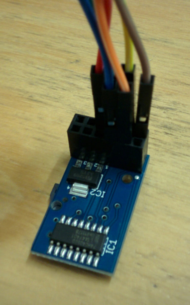
IC1 is the level-shifter
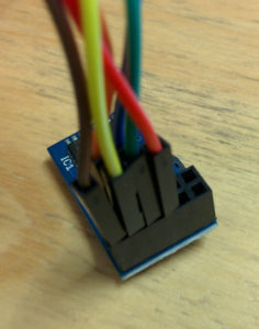
Next problem, none of the pins on the SD card reader module are labelled! I could check the RAMPS pinout, but that’s somewhat confusing because the connector on the RAMPS has 8 pins and my module has 12. After a lot of scrolling through Google images I finally found one that looks to be the same and has the pinout at this link, so it’s an HCMODU0044.
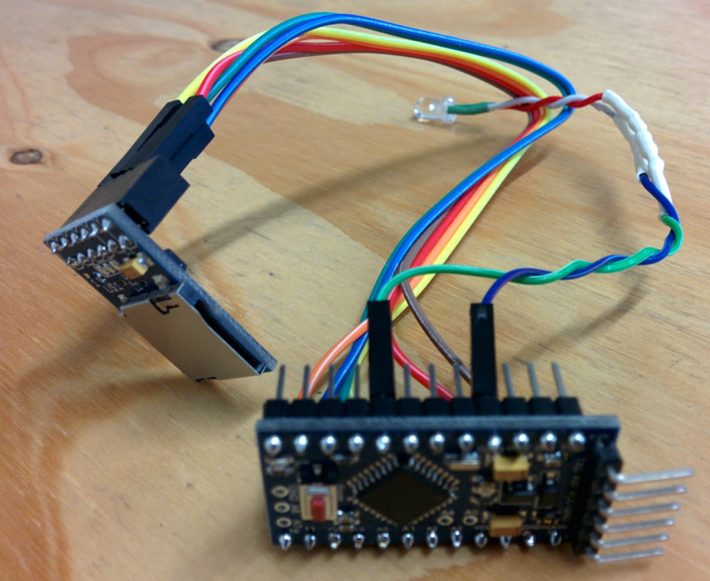
Time to do some spaghetti wiring. Connect GND and 5V to, er, GND and 5V on the Pro Mini. Connect up SCK, SO and SI from the card reader to SCK (pin 13), MISO (pin 12) and MOSI (pin 11) on the Pro Mini. CS, what to do with that? Reading the main OpenLog sketch from their github repo, there is a handy define that SD_CHIP_SELECT is pin 10. That’s probably CS then, makes sense using pins 10-13.

Finally take a random LED and 22ohm resistor from the makerspace electronic parts stock and connect it to the other GND and pin 5. This will be the status LED.
The Software
My plan here was to download the code from github and flash it. Job done. Nope, too simple! It seems that the latest code (at the time of writing) doesn’t actually build. Eventually I stumbled across this page which, as well being a good overview of using OpenLog, also contains a button to “Download OpenLog Firmware Bundle” about half way down the page.
This code compiled “better” than the latest from github, but still failed. Downloading the latest Serial Port library, as directed on the OpenLog page and I finally had a version of the code that would compile. This was using Arduino 1.6.8, the OpenLog page indicated they were using 1.6.5, so I suspect some incompatibilities have been introduced somewhere along the way.
Testing the OpenLog board using an FTDI lead and the Arudino serial console resulted in the text I typed ending up in a file on the SD card! Hurrah!
Final Thoughts
It had taken me maybe an hour to wire up and program, but that was after a couple of failed starts and a fair bit of rummaging around on the internet beforehand. It seems like a useful debugging tool to have in your box of tricks, I’m not sure why I’ve never bought or put one together before. It would be nice to build it onto a little PCB to tidy up the wiring, but that’s a project for another day….
Has it helped to fix the problem with the makerspace access control system? We don’t know yet….